1

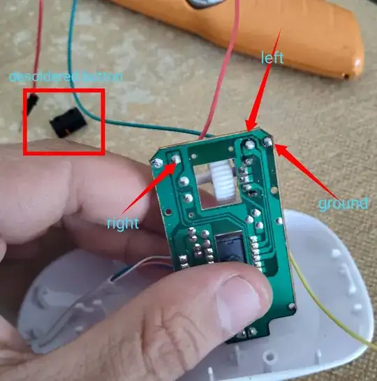
i have soldered out buttons and replaced them with wired in USB mouse. Mouse itself is connected to device. Is it possible to wire those cables to GPIO in Raspberry PI model 2. And control clicks via python? I have little project to do but must be used hardware click.

I am attaching photos what i have done so far.

image1 image2

And this page for reference: https://www.google.com/amp/s/electropeak.com/learn/tutorial-raspberry-pi-gpio-programming-using-python-full-guide/amp/

How can i put it all together? What else would i need?

Thanks for any tips. What i was thinking is connect ground to grd pin in rpi gpio and use pin 18 and resistor for left button wire to control it via python.

Current in button is 2.7V. I am newbie please shine some light over it for me.

I dont want to burn my PI on first try that is why im asking here. All tutorials i have found was about input but not much about output of GPIO Thanks!

=======PARTIAL CONCLUSION AND PROBABLY BEST ONE====================== Would be using OPTO-COUPLER, witch creates isolated environment between RPI and EXTERNAL Device such as separately powered usb mouse in my case even knowing that power is more-less than 5v (and could be manageable via GPIO itself to do what it need to be done such as pressing button?).

Its a lot safer to use OPTO-COUPLER. Instructions and video can be found here: https://youtu.be/pYENAGK8qH4

  • Ah, let me see. So you have two buttons. Press a button makes something happen. The button circuit is usually a "pull down" circuit, sending a High/Low signal to the "make something" guy. You said "current" in button is 2V7. I guess you measure the button terminal and found voltage 2V7. If you press the button, which closes/shorts the button switch, and the 2V7 goes to 0V. So now what Rpi can do is to ask GPIO send a similar output signal about 3V to 3V3 to the mouse at the button terminal where you measure 2V7. Please let me know if you more or less know what I am talking about. – tlfong01 Sep 09 '19 at 02:00
  • You might find my answer to this following question helpful (the intstructable on remote with a 2N2222 pull down circuit diagram is good): https://raspberrypi.stackexchange.com/questions/99823/using-pi-to-control-a-button-on-a-hdmi-switcher. The HDMI switch controls something different, but the trick of using a "pull down" stuff is the same. You might google/wiki to know more about the "pull down" thing. – tlfong01 Sep 09 '19 at 02:04
  • I forgot to mention that I assumed that you are using a wireless mouse, not a wired USB mouse, which is a bit more complicated. – tlfong01 Sep 09 '19 at 02:15
  • Hi all, jsotola its not unspecified problem. I dont want to use IR or Solenoids or nothing simillar. Job is simple basically if i short yellow and green cable left mouse button is pressed. If i short red and yellow then right mouse button is pressed. If none of them are not shorted its like off state. And im pretty sure its like tlfong said Its just simple send voltage to terminal to make button press. I am going to try it out and let You guys know. Thanks. How about resistor? any particullar one 330ohm should do? – Ziomuś Gorliczanin Sep 09 '19 at 02:23
  • tflong01 does it really matter if it is usb or wireless? both has to have current flow to work battery or usb powered. All it is to press that switch to short circuit (currently connect 2 wires together (green and yellow or red and yellow ) as there is no buttons no more ;) ) i am going to measure current on both states but u might be right 2.7v is when nothing is pressed and goes to zero if shorted. Also googling pull down thing is good tip need to take a look at that. – Ziomuś Gorliczanin Sep 09 '19 at 02:48
  • "does it really matter if it is usb or wireless?". Yes, it does not really matter. I am just to play very safe. There are two kind of "USB" mouses. One is wired, two power lines (red and black) and two signal lines (green and white) go inside the mouse. As I said, I don't know how this two green/white signal are doing inside the mouse. Antway, shall I assume that yours is wireless USB, with Wifi dongle inserted to your WinPC USB or Rpi USB socket/hub. And there is AAA x 2 = 3V powering the mouse? – tlfong01 Sep 09 '19 at 03:11
  • For pull up learning, I usually recommend the following: https://www.electronics-tutorials.ws/logic/pull-up-resistor.html. Of course there are many other good tutorials, for example the one from AAC (All About Circuits). There is another from UDAcity nano degree youTuble, a short video but really good. – tlfong01 Sep 09 '19 at 03:15
  • I no longer found the UdaCity youtube on pullup. But never mind, because there are many other good videos around. And for series current limiting resistors, if I am not very sure, I usually start with the safest 10K, then go down to 1k, then 512R, then 470R, then 330R etc. And let me see, 3V3 / 330R ~= 3300mA/330 ~= 10mA should be OK. – tlfong01 Sep 09 '19 at 04:43
  • You CAN NOT use GPIO as a switch! You would need to use a relay, although an opto-coupler might be possible. – Milliways Sep 09 '19 at 07:16
  • Mouse itself has its own circuit and i am not using just wires from mouse usb cable directly (5v red black wire) as mouse power is reduced on the circuit already and its powered by 2.7V on the whole circuit. Buttons if not shorted are 2.7V then in pull down state when there are getting shorted so 0v if button pressed. So just normal resistor should do to limit drawdown of the current on GPIO board. Thanks again. Milliways that is why i am here to ask and thanks for pointing it out. – Ziomuś Gorliczanin Sep 09 '19 at 07:19
  • you can connect one GPIO to another GPIO ... the mouse button switch connects to an IO pin of the mouse control chip ... just connect grounds of the mouse and RPi together ... measure the voltage of each of the two data pins ... if they are both positive then connect them with a 10k resistor ... change the output of the RPi pin ... observe the result – jsotola Sep 09 '19 at 08:08
  • quick test ... connect mouse ground to RPi ground ... attach a 10k ohm resistor to the green wire ... touch the other end of the resistor to the 3.3V power pin then touch to ground ... if you have a DVM, then also measure the current between the resistor and ground and between the resistor and 3.3V power pin – jsotola Sep 09 '19 at 08:24
  • jsotola Will do some tests but i have ran out of 10k resistors, already ordered now waiting for delivery. Sadly there is nothing local that i can buy some right now. As soon as i will know outcome of tests will be in touch. And if i do came to final conclusion will edit my question - All of You are helpfull thanks a lot! For now take care! Be back in few days. Nearly forgot - I have found this page with chip specifications it might help if i can reuse this chip to actually control X1, Y2, and Buttons ? :) http://www.teleic.com/pdf/om02-spec040210.pdf – Ziomuś Gorliczanin Sep 09 '19 at 09:13

1 Answers1

1

If the devices share a common ground another possible solution is a MOSFET e.g. BS170. These can be driven by the Pi GPIO and provide reasonable isolation. Without details of the external circuitry this can only be considered a suggestion, but the devices are readily available inexpensively (~10c) but is certainly safe.

Milliways
  • 59,890
  • 31
  • 101
  • 209