14

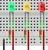
So I'm making a model that simulates traffic lights (Red, Amber, Green) so there will be three LEDS that need to be preferably extendable (I don't want them attached directly to the breadboard) but I don't even know where to start (Ok, I admit I am pretty new to all of this but do want to learn!)

Basically, I have read somewhere that I can purchase the following:

  • 26 pin ribbon cable
  • Custom PCB
  • Ribben cable socket
  • Header pins

But the problem is that I don't really want a 26 pin ribbon cable because it would just look ugly in the model. Instead I was just thinking about soldiering the PCB onto the breadboard and using (breadboard wires) connect the Pi up to the breadboard, have resistors and then finally connect the LEDS. Does this sound practical?

Hope someone can help me! :)

Alex L
  • 7,605
  • 12
  • 42
  • 53
Phorce
  • 623
  • 1
  • 8
  • 15

2 Answers2

13

You need (as minimum):

  • Red/orange/green LEDs
  • ~470 ohm resistor (1 per LED) - note that this resistance is approximate, but should work for most all standard 5mm LEDs
  • Wire
  • A breadboard
  • Pi-breadboard connector (hacked 26-pin floppy drive cable, Pi breakout kit, etc).

Your circuit will look like the following (image taken from the excellent book Raspberry Pi: A Quick-Start Guide:

Traffic lights ciruit

Ground connects to ground, and each positive connects to a GPIO pin. You can connect the Pi to the breadboard with male-female jumper cables (example), a hacked-up floppy disk drive/IDE ribbon cable (here is a tutorial), or a breakout kit such as the Pi Cobbler kit from Adafruit. Alternatively, for greatest convenience you can invest in an Adafruit Prototyping Pi Plate Kit with mini breadboard in the middle if you want to set up a semi-permanent model.

Your wires between the LEDs and breadboard can run a fair distance, so that's how you would embed the LEDs in a model.

ropable
  • 286
  • 2
  • 6
  • Thanks for the reply. One question, Where do the wires go to on the breadboard and where/how does the breadboard connect to the Pi (in your example)? – Phorce Oct 08 '12 at 23:58
  • 1
    In the diagram above, the black wire connects to the Pi's ground (pin 6), while each red wire connects to a different GPIO pin (e.g. pins 11, 12 & 13). As to the breadboard, it's exactly like the diagram - each resistor is connected to ground, the negative (cathode) leg of each LED connects to one resistor, and the positive (anode) leg of each LED connects to a GPIO pin set to output 5V. – ropable Oct 09 '12 at 14:08
  • Thank you for the reply :)! So today I went out, bought a breadboard, resistors, "jump-leads" and LEDS... I have connected all the components to the breadboard however I still don't know how to connect the breadboard to the Pi.. Someone said that I need to buy something that connects onto the pin-connector on the Pi so that I can insert the jump-lead (red, black) into the black clips that are on the component that I need to buy. Confused?? – Phorce Oct 09 '12 at 16:49
  • 1
    To connect the Pi to the breadboard, you either need a hacked-up floppy disk drive cable (hard), something like an Adafruit Pi Cobbler (better), or the prototyping kit I mentioned earlier (best IMO). I'll update my answer above. – ropable Oct 11 '12 at 02:17
  • Hey, would these be good enough?http://www.ebay.co.uk/itm/140848520724?ssPageName=STRK:MEWNX:IT&_trksid=p3984.m1497.l2649#ht_500wt_1031 thanks :) – Phorce Oct 11 '12 at 20:14
  • 1
    Yes, they'd be fine to join the breadboard to specific GPIO pins. Simplest of all methods, really. – ropable Oct 12 '12 at 05:15
  • The GPIO pins are 3.3V not 5V. They are not really powerful enough to drive LEDs near full brightness. Modern LEDs are quite efficient, so you can often get away with it if you just want to use them as an indicator. – John La Rooy Oct 16 '12 at 10:04
  • Nyc writing ..... If you put may photos of circuit then it will very very good –  Oct 30 '13 at 01:50
-2

Then you will need a 555 timer, (Chip you can buy online) then you will also need to buy a 4017(Decade Counter), a 4027(Flip flop), and a 7408(And Gate), you can all of these chips online and the truth table for the and gate can be found online to. This is if you plan on making it Hardware Led Traffic Light. And to Get the 555 to blink and Led at one second you will need a 10k and a 68k resistors.

  • 4
    On this website, it's safe to assume the questioner has a Raspberry Pi which they intend to use to control the timing and state of the LEDs – RedGrittyBrick May 21 '13 at 19:38