Computers use a system called busing to connect multiple peripheral devices to the CPU via the same set of wires. I2C and SPI are examples of busing systems used with the pi GPIO pins, which enable multiple devices on the same physical pins (managed by the internal bus) but using different addresses. Addressing is an abstraction created by the bus system protocol. It is a little bit like how you can have multiple networked applications using the same physical connection to the internet, all running simultaneously.
For example, looking at the RTC Pi Plus, one of the stackable boards from your example link:
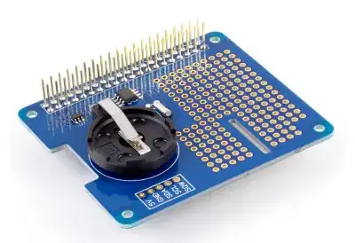
Notice on the near side the five connections in a box. These correspond to pins on the other side. They're labelled:
- 5V = Power, sharable with other devices.
- GND = Ground, also common.
- SDA and SCL = I2C bus pins; on the pi that's pins 3 and 5. You can have quite a number of devices on the I2C bus all using these same two pins for communication.
- SQW = I believe this stands for "square wave" and maybe one of our more electronically knowledgeable members will leave a nice comment explaining its purpose.
In other words, most of the pins aren't used by this board at all. They are just there to allow for stacking. The ones that it does use are all (or mostly, still don't know about SQW) sharable simultaneously with other devices.
The real limit to stacking this way is going to be the amount of power that can be supplied vs. what is consumed, not the number of pins involved. Maybe it would become a limitation if you included additional power supplies, but I think before that you'd have to move the stack outside and start using a ladder to work on it. ;)