29

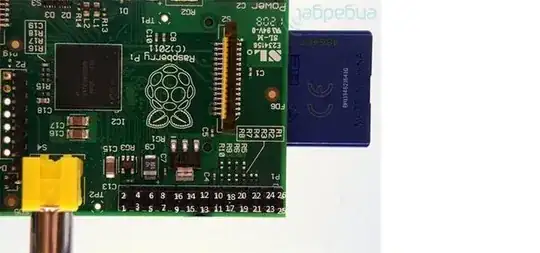
Raspberry's GPIO connector looks very similar to the old Parallel-ATA connectors. I do have several spare floppy/hdd PATA ribbon cables. Can I use these cables for GPIO? I know that GPIO has 26 pins, floppy has 34, hdd has 40, but the GPIO connector is at the edge of the board, so the connector may just overlap.

Can I use these cables, or a special cable ( like this one ) is a must?

asalamon74
  • 4,048
  • 4
  • 29
  • 31

6 Answers6

19

A 40-pin HDD cable will probably not fit. They often have pin 20 obstructed (so it must be absent from the male connector) to prevent the connector from being plugged in the wrong way round.

You can usually use a 34-pin floppy cable. But remember that a group of seven wires is usually twisted (i.e. connected in the opposite order from one end of the cable to the other.) (further explained here.) Don't forget to adjust the pinout on the slave board to compensate!

But you can always make your own cable instead.

finnw
  • 5,790
  • 3
  • 32
  • 42
  • 1
    I found an old IDC cable lying around. Works great. It doesn't have any blocked pins, and also doesn't have any twisted wires either. Makes things a little more straight forward. The downside is that it's way longer than necessary. http://www.embeddedartists.com/products/acc/acc_idc_50.php – Kibbee Jul 12 '12 at 12:44
  • 40 pin ATA cables work fine, for the 40 way GPIO on Raspberry Pi B and Pi 2. Just make sure that the connector does not have a blocked socket at pin 20. – Greenonline Jul 21 '15 at 08:52
  • Indeed, the old 40pin cables (the standard thick version) works great. The 80pin (the less older microcables version) doesn't. When I harvest these cables out of old desktop PC's, I also take out the switches, LED's and buzzer! Only the real old flat cables (20 years or so) are easy to solder. The less older ones are too thin and can be a pain to solder. So better don't cut them. – EDP Jul 21 '15 at 16:53
8

The short answer is NO you cannot use 40 pin ATA/IDE cables for GPIO on the PI.

While it is easy to get cables without the blocked pin, the main issue is that each connector internally shorts seven of the pins together. This is because in the ATA spec they are all ground, but it could be terminal for your pi.

I have verified this with a standard (80 wire) cable bought from Maplin.

The shorted pins are 2,19,22,24,26,30 and 40 which, if you are not careful will connect the 3V3 to several of the GPIO lines and a DNC (Do-Not-Connect), which is likely to fry you pi as soon as you turn it on.

If you are careful (or lucky) you can orientate it so that it only connects GPIO lines together, in which case as long as you keep all those lines at the same level (e.g. all low) then you might get away with it.
  • 3
    according to this http://www.instructables.com/id/Raspberry-Pi-GPIO-Expansion-Cable-from-a-Used-IDE-/ ony 80 wire cable pins are shorted as you described. 40 pin wire are safe. – Broncha Jul 15 '14 at 09:57
  • 2
    I just verified this on 40 wire cable, and the said pins are not shorted – Broncha Jul 15 '14 at 14:21
  • 1
    An 80 wire cable in not the same as a 40 pin. 40 pin ATA cables work fine, for the 40 way GPIO on Raspberry Pi B and Pi 2. Just make sure that the connector does not have a blocked socket at pin 20. – Greenonline Jul 21 '15 at 08:53
5

Since I know this will come up in the future. I wanted to do the same thing and used a floppy drive cable from an old computer. I have labeled what pins on the Pi correspond to what pins on the other end of the cable. Hope this helps someone in the future!

Labeled pins on the Pi

Here's a pinout of a floppy cable for reference.

Floppy Cable Pinout

Willem Ellis
  • 253
  • 3
  • 9
  • I believe you have this backwards -- notice the square solder pad on the underside of the board. That indicates pin 1. – Richard Hansen Dec 17 '12 at 18:54
  • 1
    Yes, but I'm indicating where pin 1 of the floppy cable would go. The numbers match up to which pin of the floppy drive cable you would use on the other end to access that pin. Since there's a twist in the cable. – Willem Ellis Dec 17 '12 at 22:11
4

Floppy cables used to always look like this

MB==========B=><=A

Where >< is the group of twisted wires. With a sharp knife you can trim off the wires just past the B connector and keep the MB======B part

I think some of the later ones only had two connectors, ie. no plug for the B drive. In that case you could carefully pry the connector off and move it down past the twist. This can be difficult as the locking clips are very brittle

John La Rooy
  • 11,947
  • 9
  • 47
  • 75
  • It's very easy to pry off the 7 grey cables, turn them and put them back in. Use a the length of a toothpick to push them back in. Did it many times, works great. However, 3 times out of 4, the black plastic locking clips will break when opened. If you're easy on stressing the cable when detaching connector from the Pi it won't be a problem though. – EDP Jul 21 '15 at 16:43
2

I think the best way is use a lpt (Sub-D25 ) cable from an old PC it fits perfectly end you can find it in all old computer store

https://www.facebook.com/photo.php?fbid=302451366533276&set=a.302451336533279.59880.300644370047309&type=3

http://shop.intos.de/ieos/images/produkte/closeup/33225.jpg

1

Yes you can, but it is a bit bigger.

I use flex to cut my IDE cable for the 26 pin GPIO and connect it to my motor controller based on a L9110.

It is very simple and works very well.

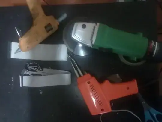
Scissors, Solder gun, Angle grinder and ribbon cables

Greenonline
  • 2,740
  • 4
  • 23
  • 36