34

I'm thinking of installing my Pi down at my wife's stables which have a 40W solar charged 12V DC lighting circuit.

Since the Pi runs at 5V I'm thinking that a quick and easy way to step down the voltage safely would be to use a microUSB mobile phone car charger such as this

Also I figure that the Pi should only be drawing about 2.5W (5V x 500mA) so the demand on the available power should be fine & the phone charger can cope with up to 850mA current so should be able to cope with a Pi.

I'll then use one of these for the display (12V so should be simple).

So the questions:

  1. Am I making sense here?
  2. Are there any other gotchas you can think of that I need to be worried about?
sraok
  • 107
  • 2
DaveG
  • 443
  • 1
  • 4
  • 6
  • 1
    Seems like a reasonable solution. – Tevo D Jun 11 '13 at 13:37
  • 1
    Yep, seems very sensible. Make sure when you've put the in-car charger inline that it's giving out the 5V you expect it to. – recantha Jun 11 '13 at 14:06
  • FYI - it worked fine ... stuck a 1A fuse inline with the charger just-in-case:

    https://lh4.googleusercontent.com/-cj2pa4nHrDk/Uo85P8VwhQI/AAAAAAAAEjY/4fclH-mJ8o0/w599-h799-no/1094070_10151559923032197_182279140_o.jpg

    – DaveG Nov 22 '13 at 11:04
  • 1
    did you go wth battery eliminator circuit? also it wasn't so clear to me how to connect this to the Pi, just put in on the 5V on the GPIO header correct? – maco1717 Dec 03 '15 at 16:03
  • I'm afraid I didn't go any further with this so I can't help you with your specific question ... you may want to ask that as a follow-up. – DaveG Dec 14 '15 at 15:37

6 Answers6

26

Go to a hobby store (or DX.com) and buy a BEC (battery eliminator circuit) intended for model aircraft. $5 gets you a very efficient switch mode voltage regulator, good for around 3A. I use these with all my Pis.

Here is an example: http://dx.com/p/hobbywing-5v-6v-3a-switch-mode-ultimate-bec-ubec-15149

spuder
  • 1,153
  • 1
  • 9
  • 14
  • Can you expand a little bit more on that. How did you connect them and which model of BEC do you use specifically. – Piotr Kula Jun 20 '13 at 08:26
  • You mean something like this?

    http://dx.com/p/8s-5a-switch-mode-ultimate-bec-ubec-45214

    – DaveG Jun 25 '13 at 15:32
  • 1
    The item that DaveG linked is suitable, yes. I use these http://dx.com/p/hobbywing-5v-6v-3a-switch-mode-ultimate-bec-ubec-15149. You just put 7-30v in one side, and 5v comes out the other. You should test the output voltage with a meter first, as some are switchable w tween 5v and 6v. – Christopher Biggs Jul 26 '13 at 23:39
  • 1
    Thanks for the awesome recommendation! I especially love how they connect to the GPIO pins out the box with no mess – Mike Demenok Mar 09 '17 at 02:46
  • Can the grounds of the 12V PSU and the BEC be connected? For example, I'm driving a MOSFET using a GPIO pin, so the source should be connected to the pi GND, but the 12V PSU should be connected to the drain (12V) and source (GND) too. Thanks for the help, I'm new to electronics. – mDroidd May 17 '18 at 11:33
10

The question seems to be inadequately answered. The best alternative would be a switching mode power supply with simple circuitry such as this: LM2596 based voltage regulator

Although 7805s work well, it's not scalable in the long run. Say you want to add a Camera Module or some other module. It'll be able to drive the circuit but cannot withstand high loads for a long time.

The data sheet of LM2596 says it can suply upto 3A. So, you'll be able to drive a few servos in addition to supplying the required power to the pi and that too at efficiences close to 80%!

You can find more info here

5

One thing to be aware of is that those chargers are not regulated, so any spikes, surges, etc will be passed on to the Pi. I would think that regulator circuit like the one below would be a safer long term solution than a car charger. For prototyping, testing etc, your car charger would be fine.

7805 circuit

Butters
  • 1,587
  • 8
  • 23
  • 7
    if you use 7805 to convert 12V into 5V it'll dissipate about 60% of power into the heat, requiring a very good heatsink. DCDC converter might be a better option. – lenik Jun 11 '13 at 22:26
  • The 40W solar panel is hooked up to a 85A-hour leisure battery via a (10A capable) charge regulator. The main lighting circuit is drawing from the first output on the charge regulator, I was intending putting the Pi on the second output of the regulator - similar to this one http://www.sunshinesolar.co.uk/khxc/gbu0-prodshow/ERG10A.html ... when would I see surges/spikes on the output (perhaps from switching on/off the lighting circuit)? – DaveG Jun 12 '13 at 08:43
  • I highly double those chargers are unregulated. I'm not ever sure how one could make an unregulated 5v, from a 12DC power source. – Gerben Jun 12 '13 at 10:13
  • 3
    @Gerben: Unregulated 5V from 12V is easy, with a voltage divider. Sure, it is a stupid solution that would create even more heat than the 7805 … – Christopher Creutzig Jun 13 '13 at 20:00
  • 1
    what the efficiency of this circuit? -1 until you edit and add the efficiency- Because he is using it on solar power that needs to save power! – Piotr Kula Jun 20 '13 at 08:04
  • Linear voltage regulators are very inefficient and gets very hot! It dissipates 7W of heat! (when 12V -> 5V) – ikkentim Nov 17 '18 at 12:11
2

This is an old post I just stumbled on however. Lets get something straight, 
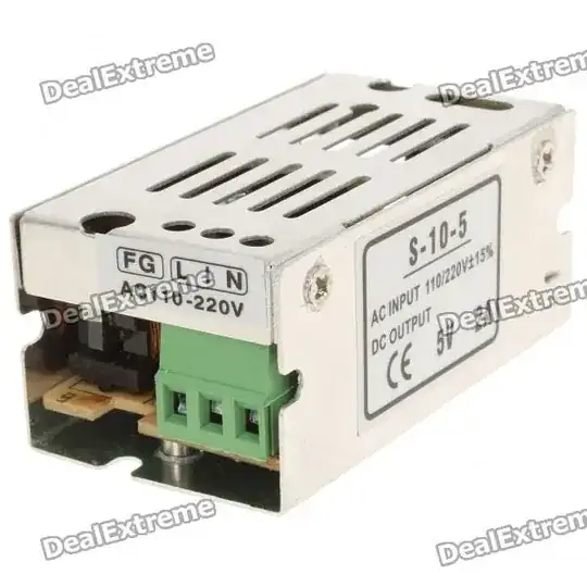
Switch mode power supplies are fine until you use them with an audio device (Radio, MP3 player etc.) Switch mode power supplies generate noise, lots of noise. In fact LF and HF radio are nearly impossible now because of them. It is easy to clean the Power supply output with a Zener, inductors and capacitors; also needed is possible ferrite cores on in and out leads and a screened case. Too much trouble?

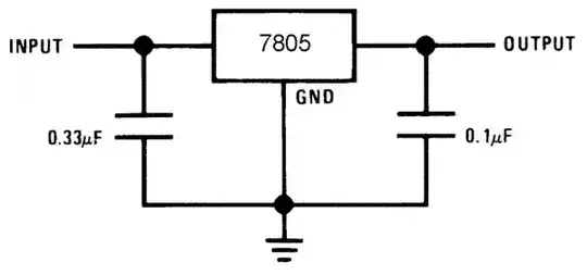
Using a regulator (voltage dropper) is a better idea but the difference between input voltage (DC) and output voltage multiplied by the drawn input current will give you the power demanded. This power has to be dissipated as heat through a heat sink.

In the case of a Raspberry Pi being powered by some kind of regulator (switch mode or dropper), with up to 13V in and 5V out at up to 2.5A gives you an idea of the power to dissipate (up to 20 Watts). That is going to be a sizable heat sink. This would be fine in non-summer months in Northern Europe, I live 70Km south of the Sahara Desert and it gets down to 25'c in Winter - the rest of the year it destroys (Chinese) electronics.

The point I am making is...... Don't care about electrical noise? Use a switch mode with good ventilation.

Need Low noise.... (Good audio, HF radio, SDR etc.) Use a regulated voltage dropper and a BIG heat sink (The car chassis is good). Use this with decent capacitors on in and out legs and you will be getting somewhere. Just a note for the Hi-Fi enthusiasts.... Quality used to measured by weight... that is a huge, heavy torroidal transformer and well designed regulated circuit, will give you as near DC as you can get to supply the circuits. Use a (light weight) Switch mode power supply and you will spend more on cleaning the DC and screening the noise than on the rest of the circuit.

So back to your post, cheap Chinese 12V to 5v Cigar lighter power converters may only supply a maximum of 1A and the electrical noise could be a problem. Right, another point, Cable size. Rule of thumb I use: at 20'c, maximum 7A per mm squared. Run this on long distances and you will see a volt drop and heating of the cable. Very short runs (say, less than 1 metre) you could use 9A per mm squared with open cable (not with others... heat dissipation!). Beyond that you are looking at tri-rated cable and that would be absolute maximum of 13A per mm squared and that's emergencies only. So no you know why lighting circuits in houses have 1 mm squared cable and a 5A fuse (some use 6A now) and 2.5 mm squared for 13A (15Abreaker).

Cheap nasty "hook-up" cable (0.5 mm square) and bad connections are not going to help with high current circuits especially in cars. Find your highest peak current and multiply it by 2 for you general cabling. This is also the same with capacitor rated voltages. Brand new electrolytic capacitors rated at 16V and connected across 12V at 20'c will probably just about do it. Raise the ambient and expect your capacitor to smooth big pulses will destroy it. Try using 25 or 35V - if you don't believe me ask Bose sound systems - they had major problems with capacitors with low ratings and bad dielectrics in all their In Car Entertainment systems (Audi comes to mind) a few years back.

http://www.vellemanusa.com/products/view/?id=500245

Darth Vader
  • 4,206
  • 24
  • 45
  • 69
TiberiusJ
  • 29
  • 1
  • 3
    "Switch mode power supplies generate noise, lots of noise." What rubbish! 95% of Pi run from Switch mode plug packs. – Milliways Jun 19 '17 at 06:37
2

They have a DC to DC converter here which is supposedly very efficient - You can find it here

Piotr Kula
  • 17,307
  • 6
  • 65
  • 104
shawaj
  • 41
  • 1
1

Remember! That wattage draw will be by the USB charger. Unfortunately they are very inefficient.

So if the USB charger says a MAX of 2A @ 5V it could use the full 10Watts regardless if the Pi is on or off. Pretty stupid but that is the trade off for being cheap and cheerful.

Switching power supplies can be up to 90% efficient. That means it will only use the power it needs. On low power the minimum wattage used when the Pi is off will be up to 9 times less than that of those USB chargers. These power supplies work very well with high wattage equipment or equipment that changes wattage very often.

You can buy a 2A 5V (10Watt) for 5 bucks here! enter image description here

Remember that it needs to be a "switching" power supply and should show the efficiency somewhere but on small power supplies the efficiency almost doesn't matter. These are also regulated, so they protect your Pi from power surges, short circuits and brownouts.

Wikipeadia

Unlike a linear power supply, the pass transistor of a switching-mode supply continually switches between low-dissipation, full-on and full-off states, and spends very little time in the high dissipation transitions, which minimizes wasted energy.

Piotr Kula
  • 17,307
  • 6
  • 65
  • 104
  • 1
    That appears to be a AC input 110/220V ... in my original question I stated that the supply I have is 12V DC so I don't think this kind of switched mode supply will work. – DaveG Jun 25 '13 at 15:36
  • 1
    @DaveG How about this one http://www.dx.com/p/dc-6v-24v-to-usb-dc-5v-3a-regulated-power-supply-module-black-314056#.U5ZemPldVfg It also comes with a usb interface so it can be connected to the pi easily – Syler Jun 10 '14 at 01:26
  • 1
    "If the USB charger says a MAX of 2A @ 5V it could use the full 10Watts regardless if the Pi is on or off" no, it won't. You might remotely see such a design for something rated for a few hundred milliamps, but something rated for 2 Amps is going to be mostly demand-controlled. The issue is more that a linear regulator from 12v to 5v has a maximum theoretical efficiency of 5/12, which is to say for every 5 watts of power used, at least 7 watts goes up in heat in the regulator. But even then, input power is proportionate to output power, not constant. – Chris Stratton Dec 04 '15 at 06:13